Abstract: sequence diagram is a diagram in the unified model language UML (Unified Model Language) used to represent the interaction between entities.
1 Introduction
When defining inter-system interfaces or inter-module interfaces, timing diagrams are very convenient to use. Work often involves negotiating with third-party systems to define interfaces or defining interfaces between multiple modules in the system. Many timing diagrams are often seen. Some timing diagrams are very beautiful, which helps readers accurately understand the business and implementation methods, while some timing diagrams are very painful to read. This article does not intend to repeat the structure and steps of the timing diagram, but only wants to explain the main problems often encountered in the timing diagram, and make a good wish: I hope that I will never encounter difficult timing diagrams in future work.
Sequence diagram is a diagram used to represent the interaction relationship between entities in the unified model language UML (Unified Model Language). English Sequence Diagram. Some people call it sequence diagrams, sequence diagrams, and sequential diagrams. Individuals are accustomed to calling them Timing diagrams are called by this name below.
There are many tools for drawing sequence diagrams, from the early Rational Rose, Sybase Power Designer, Visio, to Enterprise Architect, StarUML, and even using Typora to draw Markdown-style sequence diagrams, and now it’s a good idea to switch to Edraw according to the company’s requirements. As shown in Edraw, these tools are good, and you can draw beautiful timing diagrams with a little adaptation.
It is worth recommending that the CloudModeling drawing tool provided by the company's CloudDesign online design tool is also quite comfortable to use. It is not only easy to share in the team, but also provides a Word plug-in for importing design documents. If the timing diagram is modified, it only needs to be updated in the word document. It refreshes automatically in one click, which is very convenient and highly recommended. Website: https://clouddragon.huawei.com/uadp/home
Enter the topic below.
2 Key point 1: The context must be clear
mastered this point and succeeded more than half. If it did not do this, it was basically unclear.
Why is this sentence so cruel? Why not just draw a sequence diagram, what's the context? Because I have seen too many hateful timing diagrams that are planted on this issue.
We know that there are only two types of entities involved in the interaction in the sequence diagram, namely, Actor and Object. If even the interacting entities cannot be clearly defined and agreed upon, they will change from east to west, large and small, specific interactions. How is it possible to clarify the process, so that all readers and writers can agree.
To illustrate this problem, take the scene of the Internet of Vehicles as an example, such as the interactive sequence diagram of the remote control feature.
Sequence diagram of vehicle authorization interaction
Remote driving window interaction sequence diagram
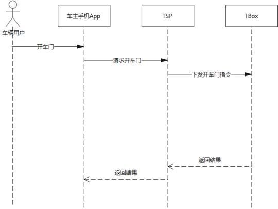
Remote open door interaction timing diagram
As shown in the figure, we see a number of similar but different expressions in the interactive entity, such as "car owner", "authorized user", "shared user" group, "mobile app" and "car owner app" "This group, "TSP platform", "TSP system" and "Car Cloud" group, and in terms of vehicles, sometimes called "vehicles" such a large granularity, sometimes called subdivided into "TBox", " Body control module", "PEPS".
Here are only three interactive sequence diagrams, and a complex system often has dozens or hundreds of them. When the author of each sequence diagram names the interactive entities as he pleases, there will be an extremely chaotic situation. In the end, it seems that every The timing diagrams all seem to make sense, but they are difficult to understand accurately when viewed together, making readers crazy.
solution: very simple, draw a context diagram, put all the interactive entities involved in the sequence diagram into it, specify their names, require all the entities in the sequence diagram to be consistent with the context diagram, and do not define new ones by yourself of. If you really need to add a new entity, first update the context and define the entity in the context diagram before you can use it.
For example, for the above-mentioned Internet of Vehicles scenario, adding a context like this can make it clearer:
In actual projects, tools can be used to achieve this consistency. For example, in the CloudModeling drawing tool, we will define a complete system context and system logic architecture view, requiring all interaction sequence diagrams to reference roles and links from this link instead of creating a new one ourselves.
3 Key point 2: Decide whether to put an entity in the sequence diagram
In the above example, in the vehicle-related entities, the granularity is sometimes called "vehicle", and sometimes it is called subdivided into "TBox", "body control module", and "PEPS". In fact, "TBox", "Body Control Module", and "PEPS" are all part of the vehicle's internal modules. Under what circumstances should the granularity of the "vehicle" be put into the sequence diagram, and under what circumstances should the "TBox" ", "Body Control Module", "PEPS" and other internal modules displayed?
personal understanding is this: Whether the entity is displayed is closely related to the business scenario and the designed object, only entities that directly interact with the designed object in the business scenario need to be placed in the sequence diagram, and indirect interaction entities should be removed .
In the above example, if the object we design is the TSP and the car owner's mobile app, then the physical part of the vehicle does not need to be expanded, only the TBox module that directly interacts with the car cloud needs to be displayed, as follows:
Remote open door interaction timing diagram
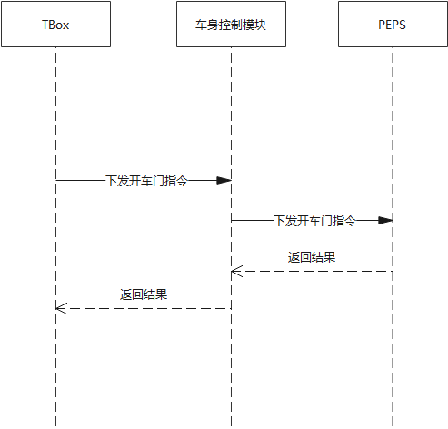
However, if the object we design is replaced by a body control module, then the interacting entities should omit the entities related to the TSP and the owner's mobile phone App, and adjust the focus to the entity that directly interacts with the body control module, for example:
Remote open door interaction timing diagram
4 Key point 3: The response message should be separated from the request message
Horizontal lines between interacting entities in the sequence diagram are used to represent messages. There are three most common types:
4.1 Synchronous Message and Return Message
The synchronization message (also called the call message) must be used in pairs with the return message. It is especially important to emphasize that the return message style must not use the synchronization message style. These are two completely different things. Synchronous message means that an entity calls an interface of another entity. The callee must implement the coding of the interface according to the process, and return according to the content of the returned message; the caller needs to implement the coding of the calling interface according to the process and respond to the return message Content is processed. In order to explain the problem more clearly, key parameters are often indicated in the message.
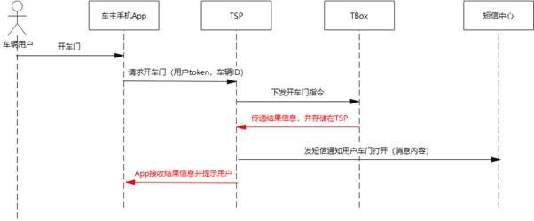
The error that I often see is that it does not distinguish between synchronization messages and return messages, which is very annoying. Sometimes you see a sequence diagram like this, pay special attention to the red message line, it seems that the "TBox" entity calls an interface of the "TSP" entity, but when I actually asked the author, I found that this is not the case, but the above The return message of the message. This kind of painting creates an illusion that both sides of the interacting entity need to implement a new interface.
4.2 Asynchronous Message
The message sender sends the information to the message receiver through the message, and then continues its own activities without waiting for the receiver to return the message.
4.3 Self-Message
Indicates that the entity itself needs to implement a process, or it can call a message from an external entity.
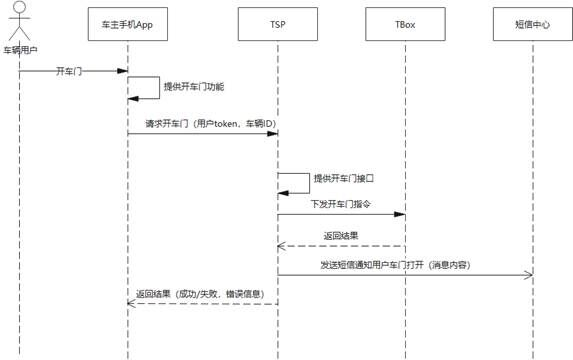
Also take the above Internet of Vehicles scenario as an example. Assuming that the design object is the TSP and the owner's mobile phone App, then we can only decompose the development tasks for these two entities. As shown in the figure, we require the "car owner's mobile phone App" to achieve "provide the door function." , Which specifically includes the processing of the message call to the TSP request to open the door and the return result; "TSP" should realize the "provide the door interface", specifically including the processing of issuing the open door instruction to the TBox and returning the result, and also includes a sending text message For the asynchronous message of the notification, the key user token and vehicle ID information should be included in the door interface request parameters provided by the TSP, and the key success/failure and error information should be included in the returned result.
Note: A new entity "SMS Center" is introduced here, which should also be added in the context map before it can be used.
Remote open door interaction timing diagram
5 Summary
Three key points: All interactive entities are put into the context, entities that do not interact directly are removed, and the response message should be separated from the request message. If you draw the timing diagram to ensure that the above three key points are achieved, I think at least I will have less complaints when I show it to everyone.
Click to follow and learn about Huawei Cloud's fresh technology for the first time~


**粗体** _斜体_ [链接](http://example.com) `代码` - 列表 > 引用。你还可以使用@来通知其他用户。