Summary of the previous situation
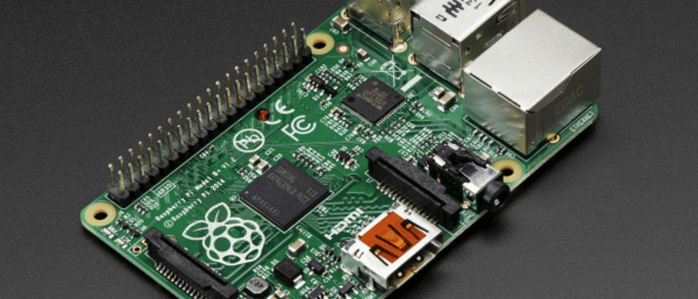
Recently, I have been thinking about using Raspberry Pi to control the motor speed. The estimated voltage of the motor is 24V and the current is 10A. In this configuration, a stepless speed controller is needed to control the motor speed. After reading the relevant controllers, the price is not expensive. Ten More bucks can make a whole piece. Then, the relevant stepless speed regulation provides PWM control.
Then speaking of speed control, generally speaking, low-power circuits, such as 5V/1A, 3V/1A, are usually connected directly to a potentiometer for control, while for high-power circuits, such as 100W, 200W In this way, a high-voltage circuit is usually required to be controlled by a low-voltage. Generally speaking, a high-voltage current circuit can be controlled by a low-voltage stepless voltage and current regulation directly through a high-power triode. But the actual amplifying circuit is still relatively complicated. I am not a professional, and I have not done in-depth research on the root cause and principle of this, so let's not talk about it for the time being. In addition, digital circuits are used to control high-power electrical appliances, so low voltages are also required to be controlled by amplifier circuits.
Based on this premise, then the question arises, how can digital circuits control the voltage and current. First of all, the adjustment principle of the physical potentiometer is to control the resistance in the circuit to control the current and voltage in the entire circuit, which is easy to understand. In the digital circuit, it is through PWM(Pulse width modulation) , which means 脉冲宽度调制 1c885e18054901faac816cd6fa076152--- in Chinese.
PWM
To understand PWM literally, it is not very easy to understand at first. I was confused at first, so I will sort it out in the way I understand.
first:
- The output of the digital circuit is all
高/低level, the high level can be assumed to be 1, the low level can be assumed to be 0, that is, there is no current and voltage flow in the circuit in the case of low level . As for the specific高level, what is the corresponding voltage, then I take the Raspberry Pi as an example, the Raspberry Pi has several pins, and some pins output3.3VVoltage, some pins output5V, then the corresponding high and low levels are:3.3:0,5:0. - Digital circuits have frequencies. In my understanding, this is how many times the current flows in a clock cycle (1 second), that is, how many times the current is divided into transfers in a clock cycle, such as 10MHZ, then it is a clock cycle. The current is divided into 10M times for delivery.
However, after the above two basic knowledge, it is easy to understand PWM. Before understanding PWM, you also need to understand a concept called duty ratio. The duty ratio means the ratio of the number of low-level outputs in a unit time to all the number of levels (high-level output times + low-level output times), such as the circuit of 10MHZ , if empty The proportion is 0.1 , then there are 1M times outputting low level, 9M times outputting high level.
The concept of PWM is that it was originally a circuit of 5V/16MA , then, I originally output a high level 10M times in a unit time, but assuming that the duty ratio is 0.8 , also That is to say, it is equivalent to 10M times of which 8M=10M*0.8 times are output low level. Then it is obvious that the current flowing per unit time is 2M=10M-8M times, that is, the actual time to transmit the current per unit time only accounts for 0.2 . That is to say, the original circuit of 5V/16MA is now transmitted in unit time 5V/16MA * 0.2 = 1V/3.2MA The purpose of buck current limiting.
Program control duty ratio
If you say Raspberry Pi, there are several interfaces that can call the library provided by the system to directly output PWM . Putting this aside, if you want to handle it yourself, use the program to control it. Similar to the following pseudocode:
 频率 = 10MHZ
一个电平在单位时间内的传送时间 = 1 / 频率
空占比 = 0.8

while True:
    输出高电平()
    持续等到高电平输出时间 = 一个电平在单位时间内的传送时间 * (1-空占比)

    输出低电平()
    持续等到低电平输出时间 = 一个电平在单位时间内的传送时间 * 空占比
In fact, there are many PWM algorithms, and there may be different restrictions in different circuit controls, such as the simplest example, such as LED light control, if the duty ratio is 0.5, then within 1 second, if the first 0.5 seconds output High level, the next 0.5 seconds output low level. Although the average voltage and current per unit time are half of the actual voltage and current, the human eye can clearly feel that the LED is flickering, because the human eye can feel that the screen does not flicker, and the screen refresh rate must at least be up to 24HZ. Therefore, it is necessary to divide the high and low levels into at least 24 parts per unit time, and then divide the time according to the duty ratio in each part, and then output the high and low levels in their own time. flat. That is to say, if the 高/低 level output according to the duty ratio is used as a basic operation, the more operations can be done per unit time, the more stable the voltage and current will be. The actual verification has been done on the Raspberry Pi, but the actual mathematical verification has not been done.
write at the end
Personally, I make a record of the whole set of control ideas. When PWM control is needed, I can directly control the operation provided by the corresponding system hardware. The main reason is that after understanding the whole set of basic reasons, things are not so mysterious.


**粗体** _斜体_ [链接](http://example.com) `代码` - 列表 > 引用。你还可以使用@来通知其他用户。