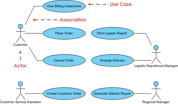
Use case diagrams are models of high-level system requirements. Use case diagrams are mainly used to visualize use cases, corresponding departments and their interactions. The diagram itself is not a use case, but a visual view of the participants and a set of related use cases. The visual model of the use case helps to understand the business process and facilitates communication with stakeholders. The use case specifications and files shown in the use case diagram constitute the key to requirements modeling.
4+1 view of UML diagram
Considering that UML diagrams can be used in different stages of the system life cycle, let's take a look at the "4+1 view" of UML diagrams. The 4+1 view provides a different perspective to classify and apply UML diagrams. The 4+1 view is essentially a way of looking at the system from the perspective of the software life cycle. Each of these views represents how to model the system. This will enable us to understand the exact location of UML diagrams and their applicability.
Different users use any real-world system. Users can be developers, testers, business personnel, analysts, and so on. Well, before designing a system, the architecture is considered from a different perspective. The most important part is to visualize the system from the perspective of different observers. The more we know, the better the system will be. This group of views is called the 4+1 view of the software architecture. UML plays an important role in defining the different perspectives of the system. These views are:
Use Case View
+4 Architecture view:
- Logial
- Implementation
- Process
- Deployment
What is a use case diagram ( use cae diagram )?
The use case model describes the functional requirements of the system according to the use cases. It is a model of the expected function of the system (use cases) and its environment (participants). Use cases enable you to correlate your needs for the system with how the system meets those needs. It consists of use cases, participants and their relationships. Use case diagrams are used for high-level design to capture the requirements of the system. It represents the function of the system and its flow. Although use case diagrams are not good candidates for forward and reverse engineering, they are still used for modeling in slightly different ways.
Because it is a very powerful planning tool, the use case model is usually used by all team members at all stages of the development cycle.
Use case diagram example
Use case diagram
Use case diagrams are essentially static in behavior. This is because they help organize and evaluate system requirements in the problem space. The behavioral aspects of the requirement are not visible in the use case diagram. Because the relationship between two use cases or between participants and use cases does not represent the concept of time, use case diagrams are classified as static diagrams. In this regard, it should be noted that use case diagrams are regarded as describing the process or behavior of the system. The process flow is part of the text file of the use cases and corresponding activity diagrams.
The use case in the use case diagram cannot be decomposed like a data flow diagram (DFD). Use case diagrams have no hierarchy or level, they are at the same level in the entire requirements model. Use case archives are a rich source of business entities that identify the final generated class.
UML other diagrams
- perform UML modeling?
- 14 UML diagram types
- What is a class diagram?
- What is a component drawing?
- What is a deployment diagram?
- What is an object graph?
- What is the package drawing?
- What is a composite structure drawing?
- What is a section view?
- What is a use case diagram?
- What is an activity diagram?
- What is a state machine diagram?
- What is a sequence diagram?
- What is a communication diagram?
- What is the interaction overview diagram?
- What is the timing diagram
- What is a UML collaboration diagram?


**粗体** _斜体_ [链接](http://example.com) `代码` - 列表 > 引用。你还可以使用@来通知其他用户。