Introduction
After the JavaScript WebGL matrix , I found that there are still some concepts to understand before realizing the three-dimensional effect, so I went to check the information and integrated it according to my own habits.
Homogeneous coordinates
Three-dimensional coordinates are theoretically enough for three components, but when looking at related programs, it is found that there will be four components. This representation is called homogeneous coordinates , which uses an n+1-dimensional vector from an original n-dimensional vector. express. For example, the homogeneous coordinates of a vector (x, y, z) can be expressed as (x, y, z, w). This representation facilitates the use of matrix operations to transform a set of points from one coordinate system to another. Homogeneous coordinates (x, y, z, w) are equivalent to three-dimensional coordinates (x/w, y/w, z/w). See here for more details.
spatial transformation
WeGL does not have a ready-made API to directly draw three-dimensional effects. It requires a series of space transformations, and finally displays in two-dimensional space (such as computer screens), which visually looks like a three-dimensional effect. Let's take a look at some of the main conversion processes.
model space
The model space is the space that describes the three-dimensional object itself, and has its own coordinate system and corresponding origin. The point coordinates here can be described according to the visible range [-1, +1] constraint in WebGL, or not according to this constraint. The custom description rules need to be converted later.
world space
After the object model is created and placed in a specific environment, the desired effect will be achieved. In addition, displacement, scaling and rotation may be performed. All these changes require a new reference coordinate system. is world space . With the world coordinate system, objects that are independent of each other will have a description of their relative positions.
Converting from model space to world space requires the use of a Model Matrix .
The 3D model matrix is similar to the 2D transformation matrix introduced in JavaScript WebGL Matrix , with the main changes being the addition and rotation of rows and columns.
 const m4 = {
  translation: (x, y, z) => {
    return [
      1, 0, 0, 0,
      0, 1, 0, 0,
      0, 0, 1, 0,
      x, y, z, 1,
    ];
  },
  // 缩放矩阵
  scaling: (x, y, z) => {
    return [
      x, 0, 0, 0,
      0, y, 0, 0,
      0, 0, z, 0,
      0, 0, 0, 1,
    ];
  },
  // 旋转矩阵
  xRotation: (angle) => {
    const c = Math.cos(angle);
    const s = Math.sin(angle);
    return [
      1,  0,  0,  0,
      0,  c,  s,  0,
      0, -s,  c,  0,
      0,  0,  0,  1,
    ];
  },
  yRotation: (angle) => {
    const c = Math.cos(angle);
    const s = Math.sin(angle);
    return [
      c, 0, s, 0,
      0, 1, 0, 0,
     -s, 0, c, 0,
      0, 0, 0, 1,
    ];
  },
  zRotation: (angle) => {
    const c = Math.cos(angle);
    const s = Math.sin(angle);
    return [
      c, s, 0, 0,
     -s, c, 0, 0,
      0, 0, 1, 0,
      0, 0, 0, 1,
    ];
  },
}
view space
When the human eye observes a cube, there will be a difference in size when viewed from a distance and from a close distance, and different faces will be seen when viewed from the left and from the right. When drawing a three-dimensional object in WebGL, it needs to Position and orientation, put the object in the correct position, the space the viewer is in is the view space .
Converting from world space to view space requires the use of a View Matrix .
In order to describe the state of an observer, the following information is required:
- Viewpoint: The position in the space where the observer is located, and the ray along the viewing direction from this position is the line of sight .
- Observation target point: The point where the observed target is located, the viewpoint and the observation target point together determine the direction of the line of sight.
- Upward direction: The upward direction of the image finally drawn on the screen, because the observer can rotate around the line of sight, so a specific reference direction is required.
The above three kinds of information together form the view matrix. The default state of the observer in WebGL is:
- Viewpoint: at the origin of the coordinate system (0, 0, 0)
- Observe the target point: the line of sight is the negative direction of the z-axis, and the observation point is (0, 0, -1)
- Up direction: the positive direction of the y-axis, (0, 1, 0)
One way to generate a view matrix:
 function setLookAt(eye, target, up) {
  const [eyeX, eyeY, eyeZ] = eye;
  const [targetX, targetY, targetZ] = target;
  const [upX, upY, upZ] = up;
  let fx, fy, fz, sx, sy, sz, ux, uy, uz;

  fx = targetX - eyeX;
  fy = targetY - eyeY;
  fz = targetZ - eyeZ;

  // 单位化
  const rlf = 1 / Math.sqrt(fx * fx + fy * fy + fz * fz);
  fx *= rlf;
  fy *= rlf;
  fz *= rlf;
  // f 与上向量的叉乘
  sx = fy * upZ - fz * upY;
  sy = fz * upX - fx * upZ;
  sz = fx * upY - fy * upX;
  // 单位化
  const rls = 1 / Math.sqrt(sx * sx + sy * sy + sz * sz);
  sx *= rls;
  sy *= rls;
  sz *= rls;

  // s 和 f 的叉乘
  ux = sy * fz - sz * fy;
  uy = sz * fx - sx * fz;
  uz = sx * fy - sy * fx;

  const m12 = sx * -eyeX + sy * -eyeY + sz * -eyeZ;
  const m13 = ux * -eyeX + uy * -eyeY + uz * -eyeZ;
  const m14 = -fx * -eyeX + -fy * -eyeY + -fz * -eyeZ;

  return [
    sx, ux, -fx, 0,
    sy, uy, -fy, 0,
    sz, uz, -fz, 0,
    m12,m13, m14, 1,
  ];
}
The cross product is used here. Through the cross product of the two vectors, the normal vector perpendicular to the two vectors can be generated, thereby constructing a coordinate system, that is, the space where the observer is located.
Here's an example with or without a custom observer in 3D:
clipping space
Based on the above example, if you rotate it, you will find that some corners disappear , because it is beyond the viewable range of WebGL.
In a WebGL program, vertex shaders convert points to a special coordinate system called clip space . Any data that extends outside the clipping space will be clipped and not rendered.
Converting from view space to clipping space requires the use of a Projection Matrix .
Visibility
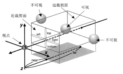
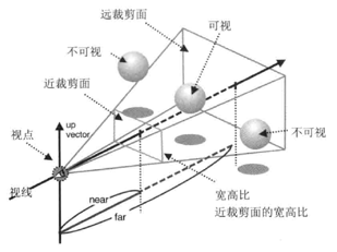
The viewing range of the human eye is limited, and WebGL similarly limits the horizontal viewing angle, vertical viewing angle, and viewing depth, which together determine the View Volume .
There are two common types of viewfields:
- Cuboid/box-shaped viewing area, generated by orthographic projection .
- Pyramid/pyramid viewing area, generated by perspective projection .
Orthographic projection can easily compare the size of objects in the scene, because the size of the object has nothing to do with its location, it should be used in technical drawing related occasions such as architectural planes. Perspective projection makes the resulting scene look deeper and more natural.
Orthographic projection
The viewing area of the orthographic projection is determined by the front and rear rectangular surfaces, which are called the near clipping plane and the far clipping plane , respectively. The space between the near clipping plane and the far clipping plane is the viewing area, and only objects in this space will be is displayed. In orthographic projection, the size of the near and far clipping planes is the same.
One way of implementing the orthographic projection matrix:
 function setOrthographicProjection(config) {
  const [left, right, bottom, top, near, far] = config;

  if (left === right || bottom === top || near === far) {
    throw "Invalid Projection";
  }

  const rw = 1 / (right - left);
  const rh = 1 / (top - bottom);
  const rd = 1 / (far - near);

  const m0 = 2 * rw;
  const m5 = 2 * rh;
  const m10 = -2 * rd;
  const m12 = -(right + left) * rw;
  const m13 = -(top + bottom) * rh;
  const m14 = -(far + near) * rd;

  return [
    m0,   0,  0,  0,
      0,  m5,  0,  0,
      0,   0, m10, 0,
    m12, m13, m14, 1,
  ];
}
Here is an example , feel the visual range change by changing the various boundaries. A more detailed explanation of the principle can be found here .
What is displayed on the Canvas is the projection of the object on the near clipping plane. If the aspect ratio of the clipping plane is different from that of the Canvas, the picture will be compressed according to the aspect ratio of the Canvas, and the object will be distorted.
perspective projection
The visual field of perspective projection is similar to that of orthographic projection, and the obvious difference is that the size of the near clipping plane and the far clipping plane are different.
One way of implementing a perspective projection matrix:
 /**
   * 透视投影
   * @param {*} config  顺序 fovy, aspect, near, far
   * fovy - 垂直视角,可是空间顶面和底面的夹角,必须大于 0
   * aspect - 近裁剪面的宽高比(宽/高)
   * near - 近裁剪面的位置,必须大于 0
   * far - 远裁剪面的位置,必须大于 0
   */
  function setPerspectiveProjection(config) {
    let [fovy, aspect, near, far] = config;

    if (near === far || aspect === 0) {
      throw "null frustum";
    }
    if (near <= 0) {
      throw "near <= 0";
    }
    if (far <= 0) {
      throw "far <= 0";
    }

    fovy = (Math.PI * fovy) / 180 / 2;
    const s = Math.sin(fovy);
    if (s === 0) {
      throw "null frustum";
    }

    const rd = 1 / (far - near);
    const ct = Math.cos(fovy) / s;

    const m0 = ct / aspect;
    const m5 = ct;
    const m10 = -(far + near) * rd;
    const m14 = -2 * near * far * rd;
    return [
      m0,   0,  0,  0,
       0,  m5,  0,  0,
       0,   0, m10,-1,
       0,   0, m14, 0,
    ];
  }
This is an example of simulating the perspective of both sides of the street, a more detailed explanation of the principle can be found here .


**粗体** _斜体_ [链接](http://example.com) `代码` - 列表 > 引用。你还可以使用@来通知其他用户。